Charge and Discharge of Capacitors with Formulas
A Capacitor is an essential component in electronics because it is able to store energy which can then used within the circuit. The button below provides an introduction on capacitor while here the main focus is to understand how the capacitor is charged and then discharged and what are the main equations that describe how the voltage and current in the capacitor behave during the charging step and the discharging step.
Figure 1 shows the schematics of a circuit containing only a battery, a resistor and a capacitor. This circuit can be used to understand the dynamics related to the charge of a capacitor.
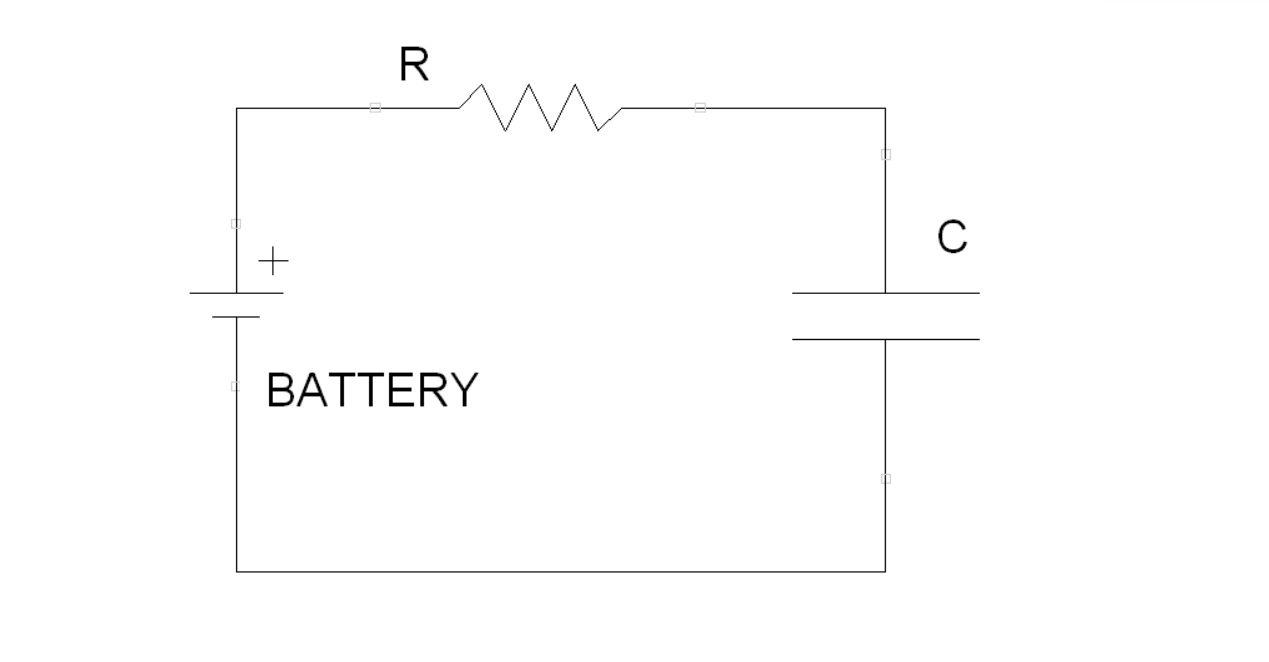
In order to create the mathematical equations for the voltage and the current some considerations need to be made:
- The Kirchhoff's voltage law states that the sum of all the voltages for this circuit need to be equal to zero, this implies that the voltage of the battery $V_b$ needs to be equal to the sum of the voltages of the resistor $V_r$ and the capacitor $V_c$. In other words, $V_b=V_r+V_c$.
- The capacitance of the capacitor is $C=\frac{Q}{V_c}$ which can be rewritten as $V_c=\frac{Q}{C}$.
- The current $i$ is the amount of charge given a certain time, this means that $i=\frac{Q}{t}$. This also means that $Q=i \cdot t$.
- The voltage on a resistor is $V_r=Ri$ where $R$ is the resistance.
- The capacitor charges over time, this means that the charge is a function $Q(t)$ that can be defined as the integral $\int_{t=0}^{T} i(t) \,dt$ where initially $t=0$ and then at the end $t=T$ where $T$ is the final time.
Charge Equations
With these consideration the equation becomes $V_b=Ri(t)+\frac{Q(t)}{C}=Ri(t)+\frac{1}{C}\int_{t=0}^{T} i(t) \,dt$. The derivative of this equation and the multiplication by $C$ creates the differential equation $RC\frac{di(t)}{dt}+i(t)=0$. This is an ordinary differential equation (ODE), which can be solved as shown below. Eq.1 is the ODE under consideration. \begin{equation} RC\frac{di(t)}{dt}+i(t)=0 \end{equation} Eq.2 moves $i(t)$ on the other side. \begin{equation} RC\frac{di(t)}{dt}=-i(t) \end{equation} Eq.3 switches $i(t)$ and $dt$. \begin{equation} RC\frac{di(t)}{i(t)}=-dt \end{equation} Eq.4 integrates both sides. \begin{equation} \int RC\frac{di(t)}{i(t)}=- \int dt \end{equation} Eq.5 solves the integrals and adds the constant $\alpha$ (remember that an integral has infinite solutions and this is described by the constant). \begin{equation} RC \ln(i(t))=-t+\alpha \end{equation} Eq.6 divides by $RC$ both sides. \begin{equation} \ln(i(t))=\frac{-t+\alpha}{RC} \end{equation} Eq.7 uses the exponential function in both sides. \begin{equation} i(t)=e^{\frac{-t+\alpha}{RC}} \end{equation} Eq.8 splits the constant terms from the terms in $t$. \begin{equation} i(t)=e^{\frac{\alpha}{RC}}e^{\frac{-t}{RC}} \end{equation} The formula has the constant $e^{\frac{\alpha}{RC}}$. Remembering that initially there is no voltage in the capacitor (i.e. $V_c=0$), this implies that at $t=0$ the voltage of the resistor is $V_r=V_b=Ri(0)$, so the equation found needs to reflect the fact that $i(0)=\frac{V_b}{R}$, as shown in Eq. 9 which substitutes the constant with $\frac{V_b}{R}$. \begin{equation} i(t)=\frac{V_b}{R}e^{\frac{-t}{RC}} \end{equation} Eq.10 substitutes $RC$ with $\tau$ which is typically called time constant because it regulates the rate of charge of the capacitor. \begin{equation} i(t)=\frac{V_b}{R}e^{\frac{-t}{\tau}} \end{equation}
Once the current equation is found, it is possible also to find the voltage remembering that $V_c(t)=\frac{1}{C}\int i(t) \,dt$. So the integral of the current needs to be calculated as shown below. Eq.11 replaces $i(t)$ with the result found above. \begin{equation} V_c(t)=\frac{1}{C}\int \frac{V_b}{R}e^{\frac{-t}{\tau}} \,dt \end{equation} Eq.12 moves constants out of the integral and replaces $RC$ with $\tau$. \begin{equation} V_c(t)=\frac{V_b}{\tau}\int e^{\frac{-t}{\tau}} \,dt \end{equation} Eq. 13 solves the integral and adds the constant $\alpha$. \begin{equation} V_c(t)=\frac{V_b}{\tau} (-\tau e^{\frac{-t}{\tau}} + \alpha) \end{equation} Eq.14 rearranges the $\tau$ terms. Remembering that at $t=0$ the voltage of the capacitor is 0 and, as we can see in Eq.14, the exponential term becomes $-1$ (because $-e^0=-1$) the constant $\alpha$ needs to be equal to $\tau$ so that $1-1=0$. \begin{equation} V_c(t)=V_b (-e^{\frac{-t}{\tau}} + \frac{\alpha}{\tau}) \end{equation} Eq. 15 shows the final voltage equation. \begin{equation} V_c(t)=V_b (1-e^{\frac{-t}{\tau}}) \end{equation}
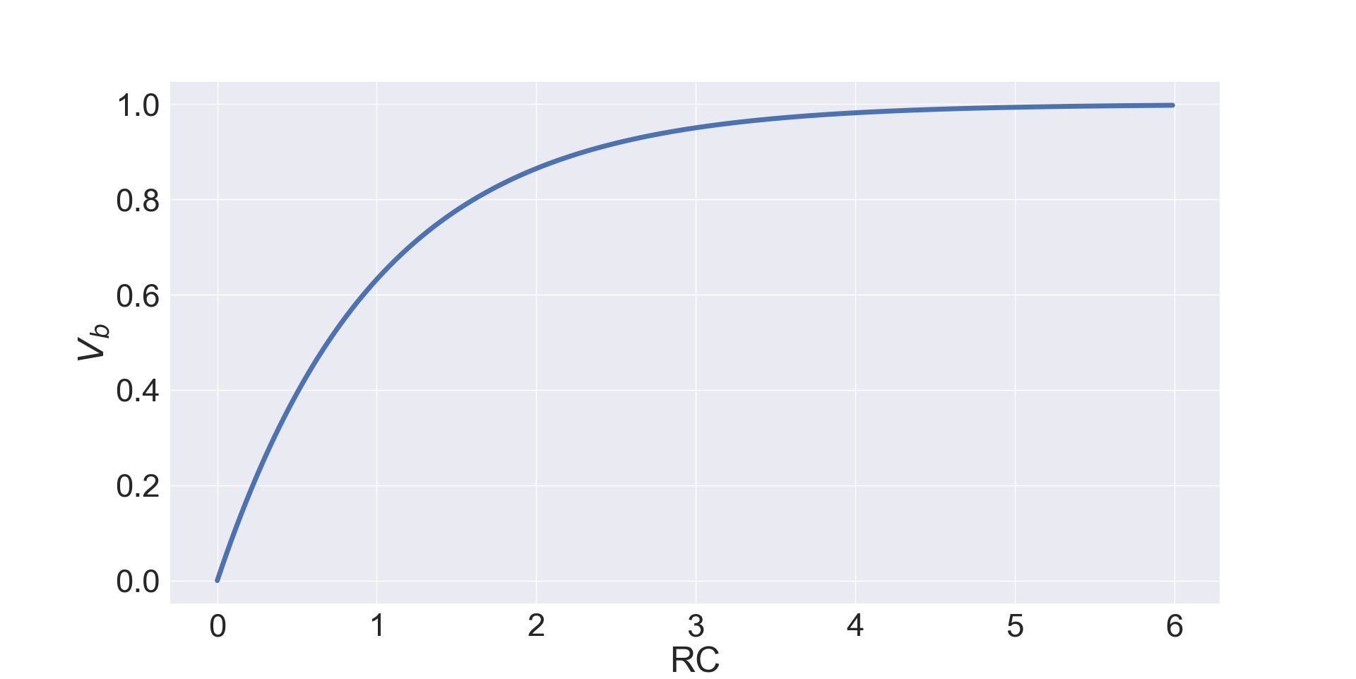
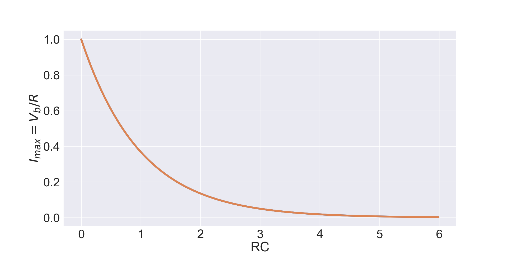
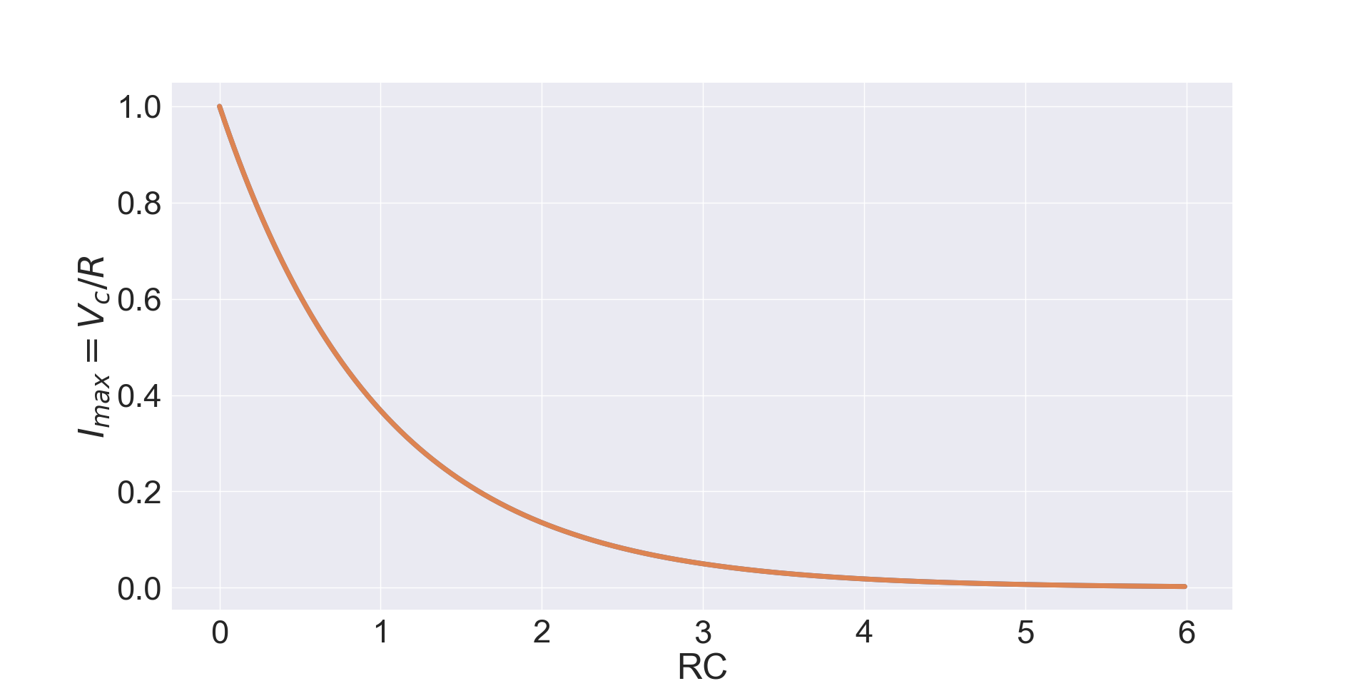
Figures 2 and 3 show respectively the exponential increase of the voltage and the exponential decrease of the current (from its initial maximum value) when the capacitor is charged, when the time reaches are around 4 or 5 time constants $\tau=RC$ the capacitor is overall fully charged.
Discharge Equations
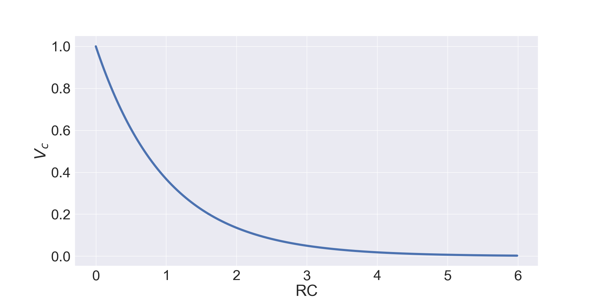
The discharge equations are similar to the charging equation because the same ODE $RC\frac{di(t)}{dt}+i(t)=0$ can be used, however the initial conditions are different because at $t=0$ the battery has been removed and the capacitor works as battery so that now $i(0)=\frac{V_c(0)}{R}$ where $V_c(0)$ is the initial capacitor voltage. Eq. 16 shows the discharge current equation. \begin{equation} i(t)=\frac{V_c(0)}{R}e^{\frac{-t}{\tau}} \end{equation} Also, given that now at $t=0$ without battery $V_r=V_c$ and $V_r=Ri(t)$ the voltage of the capacitor, as shown in Eq.17, is simply the current formula multiplied by $R$. \begin{equation} V_c(t)=V_c(0)e^{\frac{-t}{\tau}} \end{equation}Figures 4 and 5 show respectively the exponential decrease of both the voltage and the current when the capacitor is discharged. When the time reaches are around 4 or 5 time constants $\tau$ the capacitor is overall fully discharged. It is worth noticing that although the current is shown as positive it is in opposite direction respect to the one during the charging process because before the battery was on the other side of the circuit and now the capacitor acts like a battery.
All these equations and plots show that, by using different resistors and capacitors, it is possible to change the charging and discharging time of a capacitor within a circuit so these values need to be properly tuned for the required purpose of the circuit.