Intro to Capacitors
A Capacitor, called also "Condenser" or "Condensator", is another essential component in electronics given that it is able to store energy which can then used within the circuit. As shown in Figure 1, a capacitor is composed of two conductive metal plates which store electrical charges, creating a potential difference between them, when it is connected to a power supply. The difference of space between these plates and their dimensions change the properties of the capacitor.
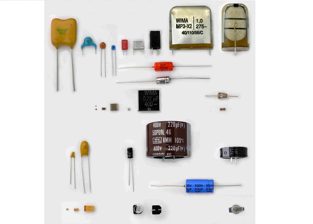
In practice, the capacitors used it electronics are much smaller and they vary in size, in shape and in the type of insulating layer between the plates: this is called Dielectric and in the previous example it is simply air but other possibilies are glass, porcelain, paper, polypropylene, polystyrene and so on. Capacitors typically have 2 terminals and each terminal is connected to one of the plates, it is important to be aware that some capacitors have a specific polarity, although not all of them are polarized, so one is a positive pin while the other is a negative pin: typically the longest is the positive although in some cases it is written on the capacitor. Figure 2 shows different types of capacitors typically used in electronics, one of the tasks is being able to select the capacitor which has properties more suitable for the circuit that needs to be created.
One of the most important properties of a capacitor is called "capacitance", it is related to the amount of electrical charge that can be stored in a capacitor and it is measured in Farads. However, the Farad is a big quantity and typically in electronics the capacitors have pico/nano/micro-Farads. Once the capacitor is connected to a power supply it begins to charge reaching the voltage of the power supply and the amount of charges depend on the capacitance. On the other hand, once it is fully charged, if the power supply is removed the capacitor begins to discharge acting like a power supply until it is empty again. The formula of the capacitance is $C=\frac{Q}{V}$ where $C$ is the capacitance, $Q$ is the electrical charge measured in Coulombs and $V$ is the voltage.
The general formula that tells what is the capacitance of a capacitor is $C=\frac{\epsilon A}{d}$ where $A$ is the Area of the plates and $d$ is the distance of the plates while $\epsilon$ is a coefficient called "permittivity" and depends on the type of material that is used as dielectric of the capacitor. Figure 3 shows the different components of the capacitor.
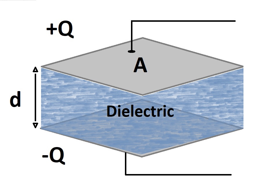
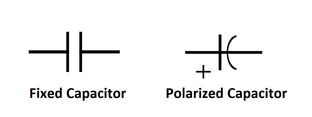
Figure 4 shows the two symbols of the capacitor typically used in schematics: the right one is used for a polarized capacitor and shows where is the position of the positive pin while the left one is used for the non-polarized capacitors but also to generally show that a capacitor is used without providing details.
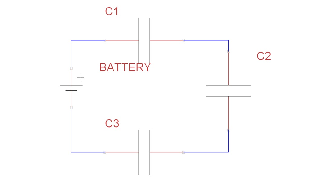
Similarly to the resistors, it is possible to use multiple capacitors in series or in parallel and their capacitance can be seen as the capacitance of a single capacitor $C_{tot}$. In case of capacitors in series, as shown in Figure 5 with 3 capacitors, the resulting inverse capacitance is equal to the sum of the inverse capacitance of all the capacitors: mathematically, for $n$ capacitors in series, this means that $\frac{1}{C_{tot}}=\frac{1}{C_1}+\frac{1}{C_2}+\cdots+\frac{1}{C_n}$.
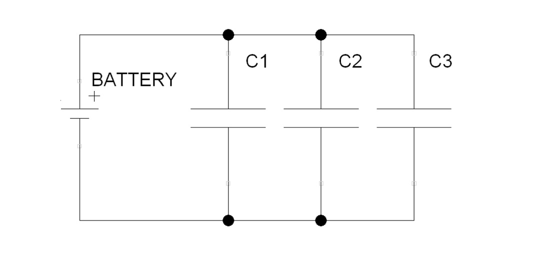
In case of capacitors in parallel, as shown in Figure 6 with 3 capacitors, the resulting capacitance is equal to the sum capacitance of all the capacitors: mathematically, for $n$ capacitors in parallel, this means that $C_{tot}=C_1+C_2+\cdots+C_n$.