Resistors, Ohm's Law and Colour Codes
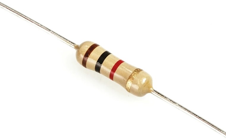
Resistors are one of the main components used in electronics. They have many different applications due to their ability of creating a resistance of the current flow which can be used to limit the amount of current in specific parts of the circuit or obtain specific voltages. The resistors have two terminals used to connec to the circuit and it does not have a specific side (it can be rotated and the resistance will be the same). Figure 1 shows an example of a resistor, these can typically be bought in packages with hundreds/thousands of them with different resistance levels.

Figure 2 shows the symbol typically used in the schematics to represent a resistor, typically near the symbol it is placed the resistance level (in Ohm) of the resistor or the name of the resistor (like R1 or R2) and then there is a legend which associates a specific name to a resistance level.

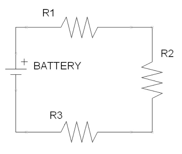
Resistors can be placed into a circuit with other resistors, they can be mainly connected in series or in parallel and any other complex configuration can be analyzed with parts that are in series or parallel. Figure 3 shows some resistors in series, the 3 resistors can be seen as a single resistor with resistance which is the sum of the 3 resistors. Mathematically, $R_{tot}=R_1+R_2+R_3$ and in general for $n$ resistors $R_{tot}=R_1+R_2+\cdots+R_n$.

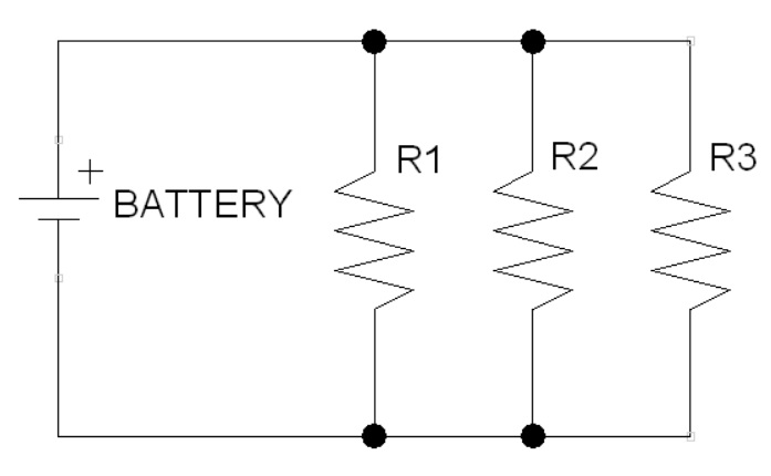
Figure 4 shows an example of circuit with parallel resistors. In this case, they can also be seen as a single resistor but the inverse of the resistance of this total resistor is equal to the sum of all the inverse resistances of the other resistors. Mathematically, $\frac{1}{R_{tot}}=\frac{1}{R_1}+\frac{1}{R_2}+\frac{1}{R_3}$ and in general for $n$ resistors $\frac{1}{R_{tot}}=\frac{1}{R_1}+\frac{1}{R_2}+\cdots+\frac{1}{R_n}$.

Ohm's Law
The Ohm's Law is an important mathematical formula which associates the voltage, the resistance and the current of a circuit. The formula states that $V=RI$: this means that, given a certain resistance $R$, the voltage is proportional to the current. It is possible to use this formula to select a specific resistor and then regulate the current flow in a part of a circuit.
The formula also provides a way of knowing the dissipated power within a resistor. The electric power of a circuit can be calculated with the formula $P=VI$ and the unit of power is in watts, by replacing $V$ with $RI$ the dissipated power within a resistor is $P=RI^2$, or by replacing $I$ with $\frac{V}{R}$ the dissipated power is $P=\frac{V^2}{R}$. This is an important value because if the current or the voltage is too large then the resistor is unable to dissipate the power and it can get damaged or burn. For this reason, there are resistors with different power ratings: the power rating provides the maximum amount of power ( in watts) that the resistor is able to handle. Figure 5 shows some examples of resistors with different power ratings, typically smaller power rating is associated with a smaller resistor.

Color Codes
The pictures of resistors provided until now show that the resistors have some colored bands on it. These bands form a color code which is used to tell some information about the resistor like the resistance (in Ohm). Figure 6 shows that the number of bands can vary: 4 and 5 bands shown in the pictures are quite common. The three main information provided for these two bands are the resistance value, the number of zeroes (a multiplier) and the level of tolerance which tells how much deviation from the nominal value is expected. Each color represents a specific digit, or number of zeroes or level of tolerance and a couple of examples are provided.
- For the 5 bands: the first 3 bands are used for the resistance value, then one is the number of zeroes and another is the level of tolerance
- For the 4 bands: the only difference is that the resistance value only uses 2 digits instead of 3.

There are also some resistors with 3 bands and 6 bands. The ones with 3 bands are like the 4 bands but do not show the tolerance level because they have a fixed value at $20\%$, while the ones with 6 bands are like the 5 bands but include also the "temperature coefficient" which tells how much the value of the resistor changes as the temperature changes: generally the resistance of all materials changes as their temperature changes, so for specific applications it is a factor that might need to be taken into account but it is not typically an issue with hobbyist circuits.